A firearm safety system, including a firearm and a uniform. The firearm includes a directional transmitter, a directional receiver, and a locking mechanism. The uniform includes an omnidirectional transmitter, an omnidirectional receiver, and an alert mechanism. The directional transmitter and directional receiver
are proximate and substantially parallel to the barrel of the firearm. The locking mechanism prevents the firearm from launching a projectile if the firearm is targeting the uniform. The alert mechanism provides feedback to an individual equipped with the uniform if the uniform is targeted by the firearm.
Certain example embodiments of this invention relate to a firearm safety system. More particularly, certain example embodiments of this invention relate to a system including a firearm and a uniform, and in which the firearm is disabled when the firearm is targeting a uniform and/or the uniform alerts the individual equipped with the uniform when if the firearm is targeting the uniform.
In combat or law enforcement, an ever-present risk is injury from friendly fire. Additionally, firearms distributed to one armed forces or law enforcement organization may end up in the possession or control of those looking to harm members of that armed forces or law enforcement organization.
Recent media reports also confirm that the U.S. armed services has trained and armed individuals who are presumed to be allies, only to find out that they are not “friendlies.” That is, in some cases, the U.S. armed services has trained and armed individuals in other countries, assuming that they would temporarily supplement and/or assume police, military, paramilitary, and/or other roles being served by U.S. servicemen and -women, e.g., as U.S. forces are drawn down. But tragically, these armed individuals have sometimes turned their weapons on their trainers, causing lives to be lost.
Even away from combat zones and law enforcement activities, licensed firearm owners may sometimes have their weapons stolen and used for ill purposes. In other cases, licensed firearm owners may have their children or other inexperienced persons play with, misappropriate, and/or misuse their weapons, possibly leading to accidents.
Thus, it will be appreciated that there is a need for a firearm safety system that addresses these and/or other concerns.
In one aspect of certain example embodiments, a system is provided that prevents a firearm from launching a projectile in the direction of an individual wearing a specific uniform.
Another aspect of certain example embodiments involves a uniform that provides feedback to an individual equipped with the uniform if the uniform is targeted by the firearm.
Another aspect of certain example embodiments relates to the uniform including an alert mechanism that provides feedback to an individual equipped with the uniform if the uniform is targeted by the firearm.
Still another aspect of certain example embodiments relates to the firearm including a locking mechanism that prevents the firearm from firing if the firearm is targeting the uniform.
In certain example embodiments, a firearm safety system is provided. A firearm comprises a directional transmitter configured to transmit a directional signal substantially parallel to and/or generally in a line of sight of the firearm. A uniform comprises an omnidirectional receiver configured to receive the directional signal transmitted by the directional transmitter; and an alert mechanism configured to output feedback to an individual equipped with the uniform in response to the omnidirectional receiver receiving the directional signal.
In certain example embodiments, a firearm safety system is provided. A uniform comprises an omnidirectional transmitter configured to transmit an omnidirectional signal. A firearm comprises a directional receiver configured to receive the omnidirectional signal transmitted by the omnidirectional transmitter; and a locking mechanism configured to prevent the firearm from firing, in response to the directional receiver receiving the omnidirectional signal.
In certain example embodiments, a firearm safety system is provided. A firearm comprises a directional transmitter configured to transmit a directional signal generally along a path in which the firearm is pointing, a directional receiver, and a locking mechanism. A uniform comprises an omnidirectional transmitter configured to transmit an omnidirectional signal; an omnidirectional receiver configured to receive the directional signal transmitted by the directional transmitter; and an alert mechanism configured to output feedback to an individual equipped with the uniform in response to the omnidirectional receiver receiving the directional signal. The directional receiver is configured to receive the omnidirectional signal transmitted by the omnidirectional transmitter. The locking mechanism is configured to prevent the firearm from firing in response to the directional receiver receiving the omnidirectional signal.
Methods of operating these and/or other systems are also contemplated herein, including for operations on a battlefield or other combat/contentious scenario, in training, etc.
The features, aspects, advantages, and example embodiments described herein may be combined to realize yet further embodiments.
These and other features and advantages may be better or more completely understood by reference to the following detailed description of example illustrative embodiments in conjunction with the drawings, of which:
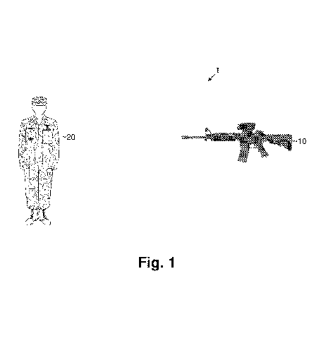
FIG. 1 is an overview of a firearm safety system in accordance with certain example embodiments;
FIG. 2 is a schematic view of the firearm safety system shown in FIG. 1 in accordance with certain example embodiments;
FIG. 3 is a partial schematic view of an illustrative portion of the firearm safety system shown in FIG. 1 in accordance with certain example embodiments;
FIG. 4 is a partial schematic view of an illustrative portion of the firearm safety system shown in FIG. 1 in accordance with certain example embodiments;
FIG. 5 is an overview of a network utilizing the firearm safety system in accordance with certain example embodiments;
FIG. 6 is a flowchart illustrating a method of protecting soldiers by disabling the firearm according to an example embodiment; and
FIG. 7 is a flowchart illustrating a method of protecting soldiers by providing feedback through the uniform according to an example embodiment; and
FIG. 8 is a flowchart illustrating a method of using information gathered by the firearm safety system for training according to an example embodiment.
Certain example embodiments relate to firearm safety systems. A detailed description of example embodiments is provided with reference to the accompanying drawings. Like reference numerals indicate like parts throughout the drawings.
Referring now more particularly to the drawings, FIG. 1 is an overview of a firearm safety system 1. In certain example embodiments, the firearm safety system 1 includes one or more uniforms 20 and one or more firearms 10.
The uniform 20 may be worn by an individual such as a member of the military (e.g., in combat, training, etc.) or law enforcement personnel (e.g., during training, the performance of duties, etc.), etc. The uniform 20 may be of or include any suitable material, such as cloth (e.g., cotton, flax, wool, ramie, silk, etc.), synthetic fiber (e.g., nylon, polyester, elastane, etc.), and/or the like. The uniform 20 may include armor designed to absorb and/or deflect slashing, bludgeoning, and penetrating attacks from weapons or projectiles. For example, the uniform 20 may include bullet resistant material such as KEVLAR™, hard-plate reinforced armor, etc.
The uniform 20 may include footwear such as shoes, boots, etc.; upper body protection such as a shirt, jacket, etc.; lower body protection such as pants; and/or head protection such as a hat, a helmet, a face shield, etc.
The firearm 10 may be any device that launches one or more projectiles. The firearm 10 may be a handgun, carbine, shotgun, rifle, etc. The firearm 10 may be single fire, semi-automatic, automatic, etc.
FIG. 2 is a schematic view of the firearm safety system 1. In certain example embodiments, the firearm 10 may include a directional transmitter 12, a directional receiver 14, and a locking mechanism 16.
The directional transmitter 12 may be any electronic device that emits a directional signal (e.g., light such as infrared light, radio waves, etc.). The directional transmitter 12 emits a directional signal in line with, parallel to, or substantially parallel to the direction of the one or more projectiles launched by the firearm 10. The directional receiver 14 may be any electronic device that senses a signal (e.g., light such as infrared light, radio waves, etc). The directional receiver 14 senses signals that are in line with, parallel to, or substantially parallel to the direction of the one or more projectiles launched by the firearm 10. More specifically, the directional receiver 14 either senses signals that are in line with, parallel to, or substantially parallel to the direction of the one or more projectiles, or senses signals in multiple directions and determines through signal processing whether the one or more signals are in line with, parallel to, or substantially parallel to the direction of the one or more projectiles. The locking mechanism 16 is in electrical communication with the directional receiver 14. As will be discussed in greater detail below, the locking mechanism 16 is configured to prevent the firearm 10 from launching the one or more projectiles, for example, in response to input from the directional receiver 12.
In certain example embodiments, the uniform 20 may include an omnidirectional receiver 22, an omnidirectional transmitter 24, and an alert mechanism 26.
The omnidirectional receiver 22 may be any electronic device that senses a signal (e.g., light such as infrared light, radio waves, etc.). The omnidirectional receiver 22 senses signals that intersect the omnidirectional receiver 22 regardless of the angle of incidence. The omnidirectional transmitter 24 may be any electronic device that emits an omnidirectional signal (e.g., light such as infrared light, radio waves, etc.). The omnidirectional transmitter 24 emits an omnidirectional signal (e.g., light such as infrared light, radio waves, etc.) in all or substantially all directions. The alert mechanism 26 is in electrical communication with the omnidirectional receiver 22. As will be discussed in greater detail below, the alert mechanism 26 is configured to provide feedback (e.g., visual, auditory, tactile, and/or the like) to the individual wearing the uniform 20 in response to input from the omnidirectional receiver 22.
In certain example embodiments, the transmitter 12 and receiver 14 in the firearm 10 may be paired with or otherwise known to the receiver 22 and transmitter 24 in the 24 in the uniform 20. For instance, the transmitter/receiver pairs may operate on a common frequency, wavelength, etc., or in a common range of frequencies, wavelengths, etc. In some cases, the receiver/transmitter pairs may be synchronized so that they vary in a predetermined, random, or other manner. Although the term “pairing” is used, it is noted that the relationship between the various transmitters/receivers may be 1:1, 1:many, many:1, or many:many.
FIG. 3 is a partial schematic view of an illustrative portion of the firearm safety system 1 in accordance with certain example embodiments. As shown in FIG. 3, the firearm 10 includes the directional transmitter 12 and the uniform 20 includes the omnidirectional receiver 22 and the alert mechanism 26. The directional transmitter 12 is located proximate to the output of the one or more projectiles launched by the firearm 10 (e.g., proximate to the barrel of the firearm 10) and emits the directional signal in line with, parallel to, or substantially parallel to the direction of the one or more projectiles launched by the firearm. As indicated above, in certain example embodiments, the directional signal emitted from the directional transmitter 12 may be infrared (IR) light, radio frequency (RF) waves, etc., and their may be a pairing or other predetermined relationship between one or more transmitters 12 and one or more receivers 22.
The omnidirectional receiver 22 includes one or more sensors and is configured to detect whether the directional signal emitted from the directional transmitter 12 is incident upon the one or more sensors. Because the directional signal emitted from the directional transmitter follows a substantially similar path as the one or more projectiles launched by the firearm 10, the omnidirectional receiver 22 is configured to detect if the uniform 20 is within the path of the one or more projectiles launched by the firearm 10. Accordingly, the omnidirectional receiver 22 is configured to detect whenever the individual equipped with the uniform 20 is targeted by a firearm 10 which includes the directional transmitter 12.
In certain example embodiments, the alert mechanism 26 of the uniform 20 provides feedback to the individual equipped with the uniform 20 to alert the individual if he or she is being targeted. More specifically, the alert mechanism 26 provides feedback to the individual in response to a determination by the omnidirectional receiver 22 that a directional signal from the directional transmitter 12 of the firearm 10 is being detected by omnidirectional receiver 22 of the uniform 20.
The alert mechanism 26 may provide tactile feedback, audible feedback, and/or visual feedback, etc. For example, alert mechanism 26 may include one or more tactile feedback devices configured to vibrate or otherwise alert the individual equipped with the uniform 20 that he or she is within the field of fire of firearm 10. In another example, the alert mechanism 26 may include one or more audio-based feedback devices (e.g., speakers) configured to produce one or more sounds or otherwise alert the individual equipped with the uniform 20 that he or she is within the field of fire of firearm 10. In another example, the alert mechanism 26 may include one or more visual feedback devices. More specifically, the uniform 20 may include a display within the individual’s field of vision or adjustable such that the display may be positioned within an individual’s field of vision (e.g., through suitably configured goggles, a head-up display (HUD), display worn by or accessible to the person, etc.). The alert mechanism 26 may include more than one or more of the aforementioned and/or other feedback devices. By providing multiple tactile feedback devices, for example, it may be possible in some circumstances to indicate a direction from which the person is “taking fire.” Similar statements also apply to audio-based and visual feedback devices.
The alert mechanism 26 may be adjustable such that the individual equipped with the uniform may adjust the type and/or intensity of the feedback. For example, the alert mechanism 26 may be configured such that an individual may choose one or more of the tactile, audible, and/or visual feedback, etc. The alert mechanism may be configured such that an individual may adjust the frequency, acceleration and/or duration the tactile feedback, the frequency and/or volume of audible feedback, the color and/or size of the visual feedback, etc. For instance, vibrations may become more intense, sounds may become louder, visual indicators may change color, etc., e.g., as the person takes more fire from a single source, as the fire comes closer to hitting the person, as more persons fire at the person, etc.
As the one or more projectiles launched by the firearm travel horizontally, the one or more projectiles will travel vertically towards the Earth due to the force of gravity. Larger horizontal distances will result in larger vertical displacement of the one or more projectiles. Therefore, in certain example embodiments, data from the directional transmitter 12 may be used to help calculate the distance between the firearm 10 and the object being targeted and use the calculated distance to approximate the path of the one or more projectiles. In this example, a processor may be configured to take the data from the directional transmitter 12 and compensate for such forces and effectively adjust the direction of the directional signal to more accurately coincide with the location upon which the one or more projectiles may impact an object. Accordingly, the directional transmitter 12 may include a storage device such as transitory or non-transitory memory to store values used to calculate the vertical displacement of the one or more projectiles (e.g., the mass of the one or more projectiles, the force exerted by the firearm 10, etc.). One or more processors may be provided, as alluded to above, to help with such calculations.
The omnidirectional receiver 22 may include one or more sensors located at different positions of the uniform 20. For example, the omnidirectional receiver 22 may include one or more sensors proximate to the head, chest, stomach, sides, back arms, hips legs, feet, etc., of the individual equipped with the uniform 20. The omnidirectional receiver 22 and the alert mechanism 26 may be configured to provide feedback based on the location of the sensor that receives the directional signal from the directional transmitter 12. For example, if a sensor located on an individual’s back receives a directional signal from the directional transmitter 12, the alert mechanism 26 may provide haptic feedback to the individual’s back so as to alert the individual that he or she is being targeted from behind. Similarly, if the alert mechanism 26 is configured to provide visual feedback, the alert mechanism 26 may indicate that the direction from which the individual is being targeted.
In certain example embodiments, the omnidirectional receiver 22 and the alert mechanism 26 are configured to immediately provide feedback to the individual as described above in response to the omnidirectional receiver 22 receiving the directional signal from the directional transmitter 12. In other example embodiments, the omnidirectional receiver 22 and the alert mechanism 26 are configured to provide feedback to the individual only if the omnidirectional receiver 22 receives the directional signal from the directional transmitter 12 for a predetermined time, e.g., in order to prevent the individual from being receiving feedback in response to the individual being only momentarily within the field of fire of the firearm 10 (e.g., because the targeted individual moved out of formation or in an unexpected way, because the person with the firearm only momentarily scanned a sightline that the person happened to be in, etc.). In certain example embodiments, the predetermined time may be a threshold minimum such as, for example, 0.5 seconds, 1 second, 2-5 seconds, etc.
Similarly, in certain example embodiments, an alert may not be triggered unless one specific individual wearing a suitably equipped uniform 20 is targeted a threshold number of times, or unless multiple individuals wearing suitably equipped uniforms 20 are targeted. For instance, a single person may be inadvertently targeted twice, three times, etc., before raising an alert. In other cases, the total number of “friendly” targets may be taken into account before an alert is raised, e.g., such that an alert may be raised if there are three, five, seven, nine, or some other number of targeted “friendlies,” regardless of whether the same or different “friendlies” are targeted at each instance.
In certain example embodiments, the time thresholds may be independent of the number of friendly targets. In other example embodiments, however, there may be some relationship between the various values. For example, the time threshold may be reduced according to a predefined pattern (e.g., a linear reduction with each friendly target, a stepwise reduction after successive thresholds targets are acquired, etc.). Similarly, if a single person is targeted for a lengthy amount of time, the threshold number of targets may be reduced in the same or similar fashion.
These approaches may be advantageous in terms of reducing “false positives.” That is, these approaches may be advantageous because they may account for real-world unpredictable scenarios. Thus, the safety system 1 may be somewhat forgiving of mistakes and/or understanding of unexpectedness within the field, but may nonetheless attempt to learn over time, or at least make educated guesses, as to who is hostile, who is bad a wielding weapons, etc.
In certain example embodiments, the directional transmitter 12 is configured to encrypt the transmitted directional signal and omnidirectional receiver 22 is configured to decrypt the directional signal transmitted by the directional transmitter 12. This may be advantageous in certain example embodiments because it may help reduce the likelihood of an enemy group scrambling signals, using their own receivers to target persons wearing uniforms 20 and/or wielding firearms 10, etc.
In certain example embodiments, the directional signal transmitted by the directional transmitter 12 includes data identifying the individual firearm 10 and/or the location of the firearm 10. The data may be packetized and may be encoded using frequency modulation, pulse width modulation, etc. The data identifying the individual firearm 10 may be stored in a memory device. The data identifying the location of the firearm 10 may be determined by a positioning system using a global positioning system (GPS), signal triangulation, etc. If the omnidirectional receiver 22 receives a directional signal from the directional transmitter 12 that includes data identifying the location of the firearm 10, the feedback mechanism may provide visual feedback indicating the location of the firearm 10 and/or an identity of the person wielding it (if known).
FIG. 4 is a partial schematic view of an illustrative portion of the firearm safety system 1 in accordance with certain example embodiments. As shown in FIG. 4, the uniform 20 includes the omnidirectional transmitter 24 and the firearm 10 includes the directional receiver 14 and the locking mechanism 16.
The omnidirectional transmitter 24 emits an omnidirectional signal in all or substantially all directions. The omnidirectional signal emitted by the omnidirectional transmitter 24 may be infrared light (IR), radio frequency (RF) waves, etc., as described above.
The directional receiver 14 is located proximate to the output of the one or more projectiles launched by the firearm 10 (e.g., proximate to the barrel of the firearm 10) and is configured to detect signals (e.g., IR signals, RF signals, etc.) which are in line with, parallel to, or substantially parallel to the direction of the one or more projectiles launched by the firearm 10.
Because directional receiver 14 is configured to detect signals emitted by the omnidirectional transmitter 24 that follow a substantially similar path as the one or more projectiles launched by the firearm 10, the directional receiver 12 is configured to detect if the uniform 20 is within the path of the one or more projectiles launched by the firearm 10. Accordingly, the directional receiver 12 is configured to detect whenever the firearm 10 is targeting an individual equipped with the uniform 20 that includes the omnidirectional transmitter 24.
Similar to the directional transmitter 12 described above with reference to FIG. 3, the directional receiver 24 is configured in certain example embodiments to adjust the vertical angle of the sensing mechanism relative to the firearm 10 to more accurately coincide with the location upon which the one or more projectiles will make contact with an object. The directional receiver 14 and the directional transceiver 12 may mechanically or electrically connected such that the vertical angle of both the directional receiver 14 and the directional transceiver 12 are adjusted simultaneously.
The locking mechanism 16 is in electrical communication with the directional receiver 24. The locking mechanism 16 may be configured to prevent the firearm 10 from launching the one or more projectiles in response to a determination by the directional receiver 14 that the uniform 20 is within the path of the one or more projectiles launched by the firearm 10. More specifically, the locking mechanism 16 may include an electrical device, mechanical device, etc., that prevents a trigger from being depressed (similar to a firearm safety) or prevents the one or more projectiles from being launched in response to a depressed trigger.
As indicated above, in certain example embodiments, the firearm 10 is configured to determine the number of times the firearm 10 has targeted the uniform 20 and the duration of each targeting. A memory medium collocated with the firearm 10 may track this data and automatically engage the locking mechanism 16 as appropriate.
In certain example embodiments, the locking mechanism 16 includes a backfire device configured to cause injury or lethality to the individual operating the firearm 10 in response to a determination by the directional receiver 14 that the firearm 10 is targeting the uniform 20. For example, a backfire device may be configured to cause injury or lethality to the individual operating the firearm 10 in response to a determination that the trigger of the firearm 10 is depressed while the firearm 10 is targeting a uniform 20. Alternatively, the backfire device may be configured to cause injury or lethality in response to a determination that the firearm 10 has targeted a uniform 20 a threshold number of times and/or for a threshold duration. Examples of backfire devices include explosives, electroshock devices, and/or devices configured to launch one or more projectiles towards the individual operating the firearm 10.
In certain example embodiments, omnidirectional transmitter 24 is configured to encrypt the transmitted omnidirectional signal and directional receiver 14 is configured to decrypt the omnidirectional signal transmitted by the omnidirectional transmitter 24.
In certain example embodiments, the uniform 20 includes one or more security features to prevent unauthorized individuals (e.g., enemy combatants) that obtain and wear the uniform 20 from transmitting the omnidirectional signal from omnidirectional transmitter 24. For example, the security feature may include a storage device that stores a password, a user interface (e.g., buttons, switches, keypads, etc.) configured to input a password, a processing device configured to determine if the password input matches the stored password, etc. In another example, the security feature may include a storage device that stores a biometric information (e.g., fingerprint, retinal pattern, etc.) that is sufficiently unique to differentiate between the authorized user of the uniform 20 and other individuals, an input device (e.g., fingerprint reader, retinal scanner, etc.) configured to input biometric information, a processing device configured to determine if the input biometric information matches the stored biometric information, etc.
In certain example embodiments, the omnidirectional transmitter 24 is configured to encrypt the transmitted omnidirectional signal and directional receiver 14 is configured to decrypt the omnidirectional signal transmitted by the omnidirectional transmitter 24.
In certain example embodiments, the omnidirectional signal transmitted by the omnidirectional directional transmitter 24 includes data identifying the individual uniform 20 and/or the location of the uniform 20. The data may be packetized and may be encoded using frequency modulation, pulse width modulation, etc. The data identifying the individual uniform 20 may be stored in a memory device. The data identifying the location of the uniform 20 may be determined by a positioning system using a global positioning system (GPS), signal triangulation, etc.
FIG. 5 is an overview of a network 100 utilizing uniforms 20 and firearms 10 of the firearm safety system 1 in accordance with certain example embodiments.
Referring to FIG. 5, the network 100 includes firearms 10, uniforms 20, and a central command location 30. Each uniform 20 and/or firearm 10 may store and/or transmit information gathered during training and/or combat operations. For example, each uniform 20 may store and/or transmit the location of the uniform 20, each instance in which the uniform 20 was targeted by a firearm 10 (or a uniform 20 moved within the field of fire of the firearm 10), the duration of time the uniform 20 was within the field of fire of the firearm 10, the location of the firearm 10, etc. The information may be encrypted may be transmitted by any suitable transmitter through radio frequency or other wireless communication methods. For example, the information may be transmitted by the omnidirectional transmitter 24 described above with reference to FIG. 4.
Each firearm 10 may store and/or transmit the location of the firearm 10, each instance in which the firearm 10 targeted a uniform 20 (or a uniform 20 moved within the field of fire of the firearm 10), the duration of time the uniform 20 was within the field of fire of the firearm 10, the location of the uniform 20, etc. The information may be encrypted may be transmitted by any suitable transmitter through radio frequency or other wireless communication methods. For example, the information may be transmitted wirelessly (e.g., through Bluetooth, near field communication, etc.) to a uniform 20 of the individual carrying the firearm 10 and the omnidirectional transmitter 24 of the uniform 20 may retransmit the information.
Information gathered by each firearm 10 and uniform 20 may be transmitted to firearms 10 and/or uniforms 20 within the network 100 and/or to a command location 30. The firearms 10 and/or uniforms 20 may create a mesh network such that information to receive and retransmit information from other firearms 10 and uniforms 20. This mesh like arrangement advantageously may be used in certain example embodiments to increase the range of transmission, decrease the power requirements needed for transmissions, relay friendly/hostile location and/or identification information to persons within the mesh, etc.
The command location 30 may include a signal receiver 31, a storage device 33, a processor 35, a display 37, etc. The signal receiver 31 may be any device configured to receive the information transmitted by the firearms 10 and/or the uniforms 20. The storage device 33 may be any device configured to store the store the received information in non-transitory form. The processor 35 may be any hardware processor configured to process, compute, and transmit data such as the received information. The command location 30 may in certain example embodiments be a central command location 30, e.g., provided in an on-station or other aircraft, temporarily deployed area, back-office potentially thousands of miles away, etc.
The processor 35 may output to the display 37 the information stored by the received from the firearms 10 and/or the uniforms 20 by the signal receiver 31 and/or the storage device 33. For example, the processor 35 output to the display 37 the location of a firearm 10 which has targeted a uniform 20. In one example embodiment, the processor 35 outputs to the display 37 the location of a firearm 10 in response to a single instance in which the firearm 10 targets a uniform 20. In another exemplary embodiment, the processor 35 outputs to the display 37 the location of a firearm 10 if the firearm 10 targets a uniform 20 a threshold number of times or for a threshold duration.
The processor 35 may execute one or more programs stored by the storage device 33. The processor 35 may apply one or more filters to the information received from the firearms 10 and/or the uniforms 20. For example, the processor 35 may perform motion analysis on the location and/or targeting information. The processor 35 may cross reference the motion analysis with approved tactical formation data.
FIG. 6 is a flowchart illustrating a method of protecting soldiers by disabling the firearm 10 according to an example embodiment. Referring to FIG. 6, the omnidirectional transmitter 24 of the uniform 20 transmits an omnidirectional signal in operation S61. The directional receiver 14 of the firearm 10 repeatedly determines whether a signal from the omnidirectional transmitter 24 is received in operation S62. If a signal from the omnidirectional transmitter 24 is received, the locking mechanism 16 prevents the one or more projectiles from being launched by the firearm 10 in operation S63. In operation S64, the firearm 10 optionally determines whether to engage the optional backfire mechanism. The firearm 10 may engage the backfire mechanism, for example, if the trigger of the firearm 10 is depressed while the directional receiver 14 receives a signal from an omnidirectional transmitter 24 of a uniform 20. Alternatively, the backfire mechanism may be engaged if the directional receiver 14 receives a signal from an omnidirectional transmitter 24 a threshold number (e.g., 1, 2, etc.) of times, for a threshold duration, etc. If the firearm 10 determines that the optional backfire mechanism should be engaged, the backfire mechanism is engaged, e.g., as described above, in operation S65.
FIG. 7 is a flowchart illustrating a method of protecting soldiers by providing feedback through the uniform 20 according to an example embodiment. Referring to FIG. 7, the directional transmitter 12 of the firearm 10 transmits a directional signal in operation S71. In operation S72, the omnidirectional receiver 22 of the uniform 20 repeatedly determines if the directional signal is received from the directional transmitter 12. If the omnidirectional receiver 22 receives the directional signal from the directional transmitter 12, the alert mechanism 26 provides feedback as described above in operation S73.
Although certain example embodiments have been described in connection with live-fire and/or hostile environments, it will be appreciated that the example techniques set forth herein may be used in connection with training and/or other simulations. For instance, troop movements, deployment patterns, etc., may be monitored; individual targeting accuracy may be gauged; responses to stimuli may be tested; etc. In this vein, the data may be related to the central command location 30 and processed to determine who is likely to panic under pressure, who needs more training as to how to handle a firearm (e.g., so as to not endanger persons moving in or out of formation, etc), and so on.
FIG. 8 is a flowchart illustrating a method of using information gathered by the firearm safety system 1 for training according to an example embodiment. The omnidirectional transmitter 24 of uniform 20 transmits an omnidirectional signal in operation S81. The directional transmitter 12 of the firearm 10 transmits a directional signal in operation S82.
In operation S83, the directional receiver 14 of the firearm 10 determines whether the omnidirectional signal is received. If the directional receiver 14 receives the omnidirectional signal, the firearm 10 stores and/or transmits information relating to the omnidirectional signal as described above in operation S84. The information stored or transmitted by the firearm 10 may include the location of the firearm 10, each instance in which the firearm 10 targeted a uniform 20 (or a uniform 20 moved within the field of fire of the firearm 10), the duration of time the uniform 20 was within the field of fire of the firearm 10, the location of the uniform 20, etc.
In operation S85, the omnidirectional receiver 22 of the uniform 20 determines whether the directional signal from the directional transmitter 12 is received. If the omnidirectional receiver 22 receives the omnidirectional signal from the directional transmitter 12, the uniform 20 stores and/or transmits information relating to the directional signal as described above in operation S86. The information stored or transmitted by the uniform 20 may include the location of the uniform 20, each instance in which the uniform 20 was targeted by a firearm 10 (or a uniform 20 moved within the field of fire of the firearm 10), the duration of time the uniform 20 was within the field of fire of the firearm 10, the location of the firearm 10, etc.
As indicated above, certain example embodiments may attempt to restrict the use of a firearm when one attempts to put the firearm in use without authorization, e.g., in situations where the firearm falls into the hands of an enemy (possibly because a presumed ally is actually a hostile person, a weapon on the battlefield is picked up by another, etc.), is stolen, and/or the like. Inputs in the form of alphanumeric codes, biometric data, and/or the like, may be used to control whether the firearm is able to fire in certain example instances as indicated above. It will be appreciated, however, that there may be civilian (or at least non-military and/or non-law enforcement related) applications for these and/or other similar techniques. For example, it will be appreciated that it would be desirable to cause a weapon to stop working if it were stolen, being used in connection with the commission of a crime, fell into the hands of a child, etc. Certain example embodiments address these and/or other needs by, among other things, providing remote monitoring systems and/or methods. In such remote monitoring systems and/or methods, a firearm may be locked when it is stowed, automatically after a period of inactivity and/or non-movement, etc. In such cases, the firearm’s location additionally or alternatively may be tracked (e.g., if the firearm has a GPS or other locating means connected thereto or associated therewith).
In order to re-enable the use of the firearm and/or at least temporarily halt tracking of the firearm, a code, biometric data, and/or the like, may be input to a control system placed on the firearm. For example, a small keypad or the like may be provided to the firearm so that a control code (e.g., a four digit code, etc.) can be entered; a thumbprint or retinal scanner can be disposed on the firearm (e.g., near the grip or elsewhere); etc. Alternatively, or in addition, a code may be entered to a remote system, e.g., by providing the same or similar input to a computer that communicates the information over a network such as the Internet to a remote server, placing a telephone call to a number dedicated to the firearm or to a general number and then providing authenticating information (such as, for example, a username and password or control code), sending an SMS or other message to a dedicated address, etc.
In certain example embodiments, when the “unlock code” is provided, the firearm may be enabled for normal operation and/or tracking of firearm may at least temporarily cease. If, however, an attempt is made to move the weapon, fire the weapon, etc., while it is still in a locked state, then the remote monitoring system may be alerted accordingly. For example, real-time positional information may be uploaded to the remote system (e.g., based on data gathered by the GPS or other locating means and through a cellular, network-based, satellite, and/or communication channel using a processor and a suitably configured transmitter collocated with or otherwise provided to the firearm).
Circuitry associated with the receipt of the lock/unlock code, GPS or other locating device, etc., may be integrated into a single chip potentially built into the firearm in a concealed and possibly difficult to access location. A chip may, for example, be at least partially pre-programmed by a manufacturer of the firearm so as to contain, for example, a read-only indication of the firearm’s serial number, make/model, year, and/or other identifying information. A unique identifier in certain example embodiments may be broadcast via a signal generator and may take the form of, for example, an RF signal, and IR signal, etc. Similarly, in certain example embodiments, the unique identifier may be telephone number that can be called, etc. The chip may, however, be programmable so that it can receive an instruction to store a new lock/unlock code, e.g., after a control code instructing the chip to accept the new lock/unlock code is entered.
This information concerning movement of the firearm, attempted use of the firearm, attempted unlocking of the firearm, etc., once detected by the remote system (e.g., as relayed to it via a detection at the firearm level), may cause the firearm’s owner or other person tasked with its monitoring to be apprised of the situation, e.g., by initiating a call from a call center, placing an automatic/automated call, sending an email or SMS or other electronic message, etc. If a firearm is suspected of being stolen, for example, then the owner can be contacted to confirm whether that is the case. If the owner confirms that the firearm has been stolen, or does not reply within a suitable predefined time period, then law enforcement personnel can be automatically notified of the suspected or reported theft. The notification to law enforcement personnel may include identifying information regarding the firearm (e.g., serial number, make, model, year, etc.), last known and/or live position date, etc. In certain example embodiments, law enforcement personnel may have access to a backend tracking system provided by the remote monitoring system’s operator and/or the like and may be provided with real-time information through a suitable computer-based user interface.
In certain example embodiments, positional data and/or status information (e.g., whether an attempt has been made to unlock the firearm, whether an attempt has been made to fire the weapon, etc.) information, may be obtained substantially in real-time by using a software application provided to a computer, smart device, call-in service, etc. For example, an App provided to a smart phone may enable real-time information about the firearm to be achieved. This may be accomplished in certain example embodiments by having the App contact a service operated in a cloud-based environment that then interfaces with the firearm directly or indirectly (e.g., through a database managed by the remote monitoring system, etc.) to obtain real-time or recent snapshot information. It thus will be appreciated that the App could be used in certain example scenarios to follow the firearm using a computer, lock/unlock it, etc. This may be facilitated by associating the serial number with, or treating it as, a telephone number that can be called into to provide instructions to the firearm (e.g., lock/unlock commands, send position information, initiate camera recording, etc.) and/or receive data back from the firearm (e.g., positional information, lock/unlock status information, reset passwords or lock/unlock codes, pictures, streaming or uploaded, video, etc.).
It will be appreciated that these techniques may, for example, enable firearms to be remotely activated or deactivated. Thus, if a child plays with a gun, it may be safetied automatically and/or not enabled for firing upon detected movement, receipt of a remote locking signal (which could be automatically generated from a remote source and/or by or on behalf of the firearm’s owner, etc.), and/or the like. Similarly, if a firearm is detected as being close to a crime that is or was being committed, it may be deactivated while the crime is in progress and/or shortly thereafter to attempt to reduce the likelihood that it is used to cause more harm, etc.
It will be appreciated, then, that a remote monitoring service similar to those used in connection with house alarms may be provided for firearms. An “ADT-like” system may be provided, for example, to help ensure that guns are locked and cannot be used without being unlocked, that they can be shut down remotely upon the detection of a problem or suspected misuse, etc. Overriding gun control in this way may be advantageous in terms of protecting children and/or other untrained individuals, thwarting crimes, etc. It also may be done in the context of a private company that is separate from the government, thereby addressing civil liberties and/or other concerns in some cases. In some cases, the security service may charge a monthly, annual, or other service fee for providing monitoring services, making the above-described or other similar App available, maintaining a log of positional and/or status information, etc. In other cases, the App may be provided by the firearm’s manufacturer or by a third-party that is unrelated to a subscription-type service and not an official part of the government.
In certain example embodiments, the firearm may be provided with a small camera or the like. The camera may be provided on or along a path at which a sight is provided. The camera may be in communication with the control chip mentioned above and may be selectively activated/deactivated for a number of different example purposes. The camera may be used in certain instances whenever the firearm is unlocked. In other example instances, the camera may be used unless it is expressly turned off by the user. In certain example instances, the camera may be used to record movements of the firearm, e.g., in the event that there is an attempted and/or suspected unauthorized movement and/or use. The data may be stored to a memory medium local to the device and uploaded and/or streamed to a remote server. The security monitoring system may enable “live look-ins” to authorized individuals such as, for example, the owner (through an App of the type described above), law enforcement in the event that the firearm is suspected as having been stolen or being used to commit a crime (e.g., to aid in locating the firearm, etc.), etc. Recorded data may also be useful for training purposes and/or to generate mementos of target practice, hunting expeditions, skeet shooting competitions, and/or the like. In terms of training, for example, X- and Y-axes and/or other targeting information may be superimposed on the video, e.g., to help the person determine whether they are consistently off in a particular direction and/or by a particular amount, to diagnose inconsistent trigger releases and/or muscle movements, etc. The camera can also be used to help “sight-in” a particular sight, etc., if such horizontal and/or vertical displacement data is known or can be deduced from the recording. In certain example embodiments, a button may be provided and/or the keypad may be used to turn the camera on and off, as desired. In certain example embodiments, the camera may be controlled such that it takes a picture (or burst of a predetermined number of pictures) and/or video (e.g., of a predetermined time length) any time the trigger is pulled, the firearm is suspected of being stolen, etc. This information may be accessible via the App, and may be verified in certain example scenarios by an independent verification agency, e.g., to help provide evidence when an intruder is shot, an accident occurs, a tragedy is carried out, etc.
In certain example embodiments, a firearm therefore may comprise: at least one processor; a transceiver controllable by the at least one processor; and a locking mechanism configured to prevent the firearm from firing. The transceiver is configured to: transmit positional data of the firearm based on instructions from the at least one processor, and receive from a remote source lock and unlock codes that, when processed by the at least one processor, respectively prevent and enable operation of the firearm. The positional data may be obtained through a GPS module, cellular triangulation techniques, and/or any other suitable locating means. The lock and unlock codes may be provided by a cellular, packet switched, and/or other network. In certain example embodiments, a monitoring call-in center and/or authorized individual may place a telephone call, send an email or SMS message, and/or otherwise transmit a message to a firearm to convey a lock/unlock code.
A firearm safety system may be provided, as well. The system may comprise at least one processor, and either a plurality of these and/or other firearms or connections thereto. A database stores a record for each said firearm, with each said record including contact information (e.g., telephone number, email address, etc.) for at least one person (e.g., an owner of the firearm, person charged with its custody, etc.). An alert module of the system may be configured to, in cooperation with the at least one processor, receive lock and unlock codes for the firearms and transmit received lock and unlock codes to the firearms when provided over a communication link from a verified user, and generate and transmit alert messages using the contact information when unauthorized and/or unexpected uses and/or movements of the respective firearms are detected. For instance, the alert module may be further configured to automatically send a lock signal to a firearm when an unauthorized and/or unexpected use and/or movement is detected. Related methods of operating the firearms and/or systems also are contemplated herein.
The forgoing example embodiments are intended to provide an understanding of the disclosure to one of ordinary skill in the art. The forgoing description is not intended to limit the inventive concept described in this application, the scope of which is defined in the following claims.
Publication number: 20150241153
Type: Application
Filed: Mar 22, 2013
Publication Date: Aug 27, 2015
Inventor: Aris MARDIROSSIAN (Potomac, MD)
Application Number: 13/849,322
International Classification: F41A 17/08 (20060101); F41H 13/00 (20060101);
1. A firearm safety system, comprising:
2. The firearm safety system of claim 1, wherein the directional signal is transmitted in the infrared spectrum.
3. The firearm safety system of claim 1, wherein the alert mechanism is configured to output feedback in response to the omnidirectional receiver receiving the directional signal a number of times that exceeds a first threshold and/or for a duration that exceeds a second threshold.
4. The firearm safety system of claim 1, wherein the alert mechanism is configured to generate haptic feedback.
5. The firearm safety system of claim 1, wherein the alert mechanism is configured to generate audible feedback.
6. The firearm safety system of claim 1, wherein the uniform further comprises a display and the alert mechanism is configured to output visual feedback on the display in response to the omnidirectional receiver receiving the directional signal.
7. The firearm safety system of claim 6, wherein:
8. The firearm safety system of claim 1, wherein the omnidirectional receiver comprises a plurality of sensors and the alert mechanism is configured to generate haptic feedback proximate to the sensor that detects the directional signal.
9. The firearm safety system of claim 1, wherein the directional transmitter is configured to encrypt the directional signal and the omnidirectional receiver is configured to decrypt the directional signal.
10. A firearm safety system, comprising:
11. The firearm safety system of claim 10, wherein the omnidirectional transmitter operates in the infrared spectrum.
12. The firearm safety system of claim 10, wherein the omnidirectional transmitter operates in radio frequencies.
13. The firearm safety system of claim 10, wherein the locking mechanism further comprises a backfire mechanism configured to cause injury to an individual operating the firearm when activated.
14. The firearm safety system of claim 13, wherein the firearm further comprises a trigger and the backfire mechanism is configured to cause injury to the individual operating the firearm in response to the trigger being depressed while the firearm is targeting the uniform.
15. The firearm safety system of claim 13, wherein the backfire mechanism comprises an explosive.
16. The firearm safety system of claim 13, wherein the backfire mechanism comprises electroshock devices configured to deliver a shock to the individual operating the firearm.
17. The firearm safety system of claim 13, wherein the backfire mechanism is configured to automatically engage in response to the firearm targeting the uniform a number of times that exceeds a first threshold and/or for a duration that exceeds a second threshold.
18. A firearm safety system, comprising:
19. A firearm safety system of claim 18, wherein the directional receiver is further configured to store information regarding signals received by the directional receiver.
20. A firearm safety system of claim 18, wherein the omnidirectional receiver is further configured to store information regarding signals received by the omnidirectional receiver.
21. A firearm, comprising:
22. A firearm safety system, comprising:
23. The system of claim 22, wherein the alert module is further configured to automatically send a lock signal to a firearm when an unauthorized and/or unexpected use and/or movement is detected.
24. The system of claim 22, wherein lock and unlock codes are transmittable to the firearms via cellular and/or packet switched networks.
25. The system of claim 22, wherein the contact information includes a telephone number.